Raspberry Pi Pico has been designed to be a low cost yet flexible development platform for RP2040, with the followingkey features:• RP2040 microcontroller with 2MB Flash
• Micro-USB B port for power and data (and for reprogramming the Flash)
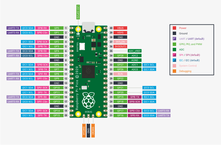
• 40 pin 21×51 'DIP' style 1mm thick PCB with 0.1" through-hole pins also with edge castellations
◦Exposes 26 multi-function 3.3V General Purpose I/O (GPIO)
◦23 GPIO are digital-only and 3 are ADC capable
◦Can be surface mounted as a module
• 3-pin ARM Serial Wire Debug (SWD) port
• Simple yet highly flexible power supply architecture
◦Various options for easily powering the unit from micro-USB, external supplies or batteries
• High quality, low cost, high availability
• Comprehensive SDK, software examples and documentation
For full details of the RP2040 microcontroller, however the headline features are:
• Dual-core cortex M0+ at up to 133MHz◦On-chip PLL allows variable core frequency
• 264kB multi-bank high performance SRAM• External Quad-SPI Flash with eXecute In Place (XIP) and 16kB on-chip cache
• High performance full-crossbar bus fabric
• On-board USB1.1 (device or host)
• 30 multi-function General Purpose IO (4 can be used for ADC)
◦1.8-3.3V IO Voltage (NOTE Pico IO voltage is fixed at 3.3V)
• 12-bit 500ksps logue to Digital Converter (ADC)
• Various digital peripherals
◦2 × UART, 2 × I2C, 2 × SPI, 16 × PWM channels
◦1 × Timer with 4 alarms, 1 × Real Time Counter
• 2 × Programmable IO (PIO) blocks, 8 state machines total
◦Flexible, user-programmable high-speed IO
◦Can emulate interfaces such as SD Card and VGA
Pico provides minimal (yet flexible) external circuitry to support the RP2040 chip: flash (Winbond W25Q16JV), crystal,power supplies and decoupling, and USB connector. The majority of the RP2040 microcontroller pins are brought to theuser IO pins on the left and right edge of the board. Four RP2040 IO are used for internal functions - driving an LED, onboard Switched Mode Power Supply (SMPS) power control and sensing the system voltages.
Pico has been designed to use either soldered 0.1" pin-headers (it is one 0.1" pitch wider than a standard 40-pin DIPpackage) or can be used as a surface mountable 'module', as the user IO pins are also castellated. There are SMT padsunderneath the USB connector and BOOTSEL button, which allow these signals to be accessed if used as a reflowsoldered SMT module
If you are interested in our products,or want to get PDF data sheets.Please feel free to contact us.
--OEM services/Hard-to-find parts souring.


